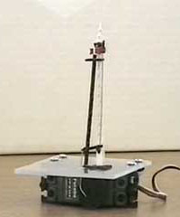
As an exercise in using microcontrollers, I decided to write a program to drive a model railway signal. Rather than use a solenoid to bang the signal up and down quickly, which is the normal method, I chose to use a radio control servo so that the signal would move at about the same speed as a real one. For good measure, I got it to bounce at each end of the travel, simulating inertia and slack in the system. Other people have done this, but trying it oneself is a challenge.
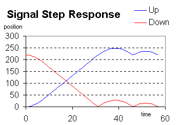
At first sight the mathematics of the graph below look quite complicated, but if you concentrate on the difference between successive positions a pattern emerges. The differences run 1, 2, 3, 4, 5, 6, 7, 8 while the signal is accelerating, stay at 8 for constant speed, then count back down to -8 when the signal goes ballistic. There's then a bounce with similar characteristics. Check out the source code if you want to see how this was implemented.

The signal is a Ratio kit. The servo is a standard Futaba S148. I connected the two with a link of nickel-silver wire, adjusted by trial-and-error to get the correct range of travel. The microcontoller is a PIC 16F84a, which has 13 input/output pins so it could run up to 6 signals in theory. I used a microcontroller development board, not shown in the pictures, to test the system. It has a variety of switches, LEDs, analogue inputs, etc, but basically all that is needed is a switch. You also need a 4MHz crystal and a 5V supply, which can run the servo and the microcontroller.
After this I modified the program so it can operate three signals at once (making the code a lot more complex), and used a 12F629 8-pin microcontroller. It is now installed on my railway.
