In session 2003/4 three of my BTech students at Bell College were working on various projects involving a robot, a toy car using infra-red for remote-control, and a tilt and pan controller for a camera. As an exercise in using microcontrollers, I decided to combine parts of all three to create a robot with an onboard camera. I was inspired by the success of the robots sent to Mars. The robot uses -
- two motor/gearbox units kindly donated by ex-student Marc Schofield. These came with a partwork magazine.
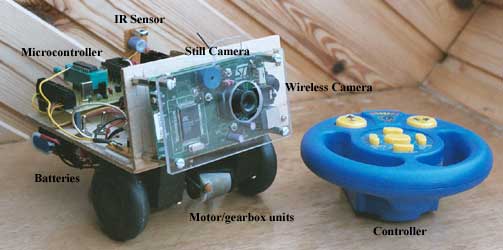
- the infra red sensor from a toy car, along with its remote control.
- a digital camera donated to the college by ST Microelectronics. This is an evaluation unit for developers.
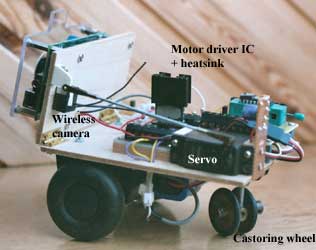
- a wireless video camera. This is tiny, and runs off a 9V battery. The picture quality isn't brilliant, but for better results we would require something bigger and heavier.
- a servo to tilt the cameras. Panning is done by rotating the whole robot.
The robot is controlled by a PIC 16F84a microcontroller. It interprets the signal from the IR sensor, operates the motors by pulse width modulation, drives the servo for tilting the cameras, and triggers the shutter release on the still camera. At first a consequence of trying to do all these at once was that interrupts made the servo judder whenever a button was pressed on the remote. I solved this by only sending a signal to the servo when it was to be moved instead of once every 20ms. This seems to work OK. The servo position is stored in flash memory; when the robot is switched on it retrieves the last known position from memory and pulses the servo.
A single 4.8V NiCad battery drives everything except the wireless camera. I've had no problems with motor switching noise upsetting any of the other devices, but I plan to separate the power supply for the motor from the rest of the circuits, just to be on the safe side.
I had to do a little "reverse engineering" to make use of the car remote control. An infra red sensor was connected to a digital storage scope and I recorded the signal transmitted for each of the nine buttons. This is a 40kHz signal modulated by a string of pulses. Each pulse is the same length, but the gap between them is either short or long, indicating a one or a zero. The codes are all eight bits long. It was a simple matter to write an interrupt-driven program to interpret the signal.
At the moment the buttons trigger one of the following -
- Increase speed
- Decrease speed, or increase speed backwards
- Increase speed of left motor and decrease speed of right motor
- Decrease speed of left motor and increase speed of right motor
- Straighten up
- Tilt cameras up
- Tilt cameras down
- Take picture
- STOP!
The controls don't make the robot very easy to drive. I suspect one motor is more powerful than the other as the robot curves to one side when it should be running straight. Also, the castoring back wheel is a bit sticky and tends to make the robot swerve off at random angles. In future, I plan to control the robot with a joystick on a computer. A slider on screen could operate the camera tilt. Watch this space!
The pictures below were taken by the still camera. The video shows the robot in (somewhat erratic) operation on the boardroom table, along with its creator. The pale line down the right hand edge of the on-board video is the edge of the clear plastic cover on the still camera.

