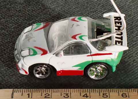
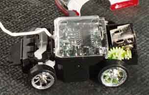
This is an extremely small radio control racing car which we dissected in the name of science. It was donated for the greater good of mankind by student Richard Crossan after it had passed away. It lead a short life but a merry one.
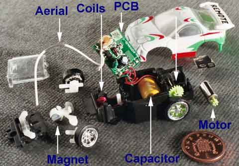
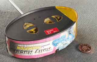
The cause of death is a short circuit in the capacitor, the yellow device shown above. This is charged up from three 'AA' batteries in the transmitter, seen below, and carries enough charge to keep the car going for a short while. Capacitors can be charged faster and more often than rechargeable batteries. Usually. We have heard of someone who fitted a larger capacitor to his car which made it run faster and longer. Then it caught fire.
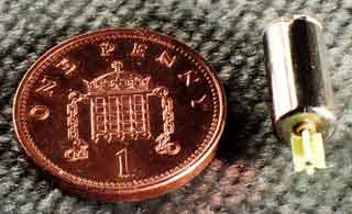
The motor has to be the smallest I have ever seen. The steering is operated by two coils of very fine wire, on either side of a magnet attached to the front wheels. A spring returns the steering wheels to the middle position when the coils are not energised. There is an adjustment underneath the car for centering.
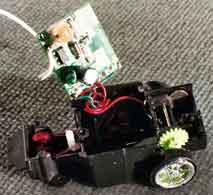
With the capacitor removed, the car could be operated as long as it stayed on the charger, located under the translucent yellow cover on the right of the transmitter. A new capacitor would allow the car to rise from the dead. However, I have other plans - watch this space.
Can you guess what I'm thinking?
Technical Stuff
Radio control cars like this come in two variants, 27MHz and 40MHz. These are the frequencies cleared for legal use with cars and boats in the UK. (Planes can use 27MHz and 35MHz.) There are multiple channels available within these bands, but this car doesn't have a receiver crystal so it probably won't have the selectivity to discriminate between different channels. The transmitter crystal has a 27.145MHz crystal, but I measured the signal frequency at 27.47MHz on a storage scope. Both figures may actually be correct - I don't know enough about radio communications to say for sure.
The transmitter seems to emit a stream of 340usec pulses, spaced out by 340usec, for as long as one of the buttons is pressed. The signal starts with 3 long pulses (1.12msec), 340usec apart. When the reverse button is pressed, 10 short pulses are followed by 4 long pulses. There must be a code for the other three buttons as well, I just haven't been able to work it out yet.
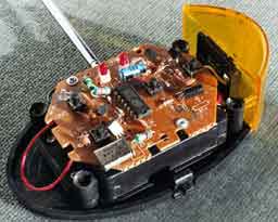
The transmitter uses a single 14-pin IC, which is probably intended for a variety of applications as three pins (6, 7 and 13) aren't connected. In particular, pin 13 has an output which looks as if it is intended for infra red transmission, as it is a modulated 39kHz signal.
Pins 4, 5, 14 and 1 are connected to the forwards, reverse, right and left buttons. Each of these shorts the pin to ground. It should be a simple matter to connect an alternative input to these pins, for example to control the motor speed with pulse width modulation. It may also be possible to use PWM to give a steering angle other than full left and full right, but friction and stiction may make this impractical.