Calculate the compression ratio of an IC engine
The compression ratio of an engine is the ratio between the cylinder volume above the piston at bottom dead centre (Vbdc) and the volume above the piston at top dead centre (Vtdc). Vbdc is Vtdc plus the swept cylinder volume (Vsw) which is the swept cylinder volume i.e. the engine capacity divided by the number of cylinders.
Vsw + Vtdc
When you know Vtdc it’s easy to calculate
compression ratio as it’s just ────────
Vtdc
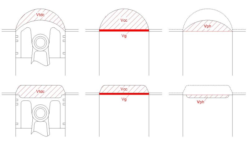
It might seem that at TDC all that is needed is the combustion chamber volume (Vcc) but that is not normally the case. As can be seen in the figures, the volume at TDC (Vtdc) needs to take in account the volume of the hole in the gasket (Vg) and the volume occupied by the piston head (Vph). If the piston is absolutely flat and level with the deck (top surface of the cylinder block) then Vph = 0.
In the upper figure, with the piston projecting into the combustion chamber,
Vtdc = Vcc + Vg – Vph
but in the lower one Vtdc = Vcc + Vg + Vph.
When you use the method, described later, for measuring Vph it automatically deals with the sign of Vph and can handle a situation where part of the piston head is above the deck and part below.
The measurements you will need
Bore of the cylinder (B).
Stroke of the engine (S).
Compressed gasket thickness (Gt).
In the case of a solid gasket the uncompressed thickness is negligibly larger than when compressed but a new composite gasket may compress by
a
significant amount when the head is torqued down. If you have an old one of the same construction then its thickness should be accurate enough.
Bore of the gasket (Gb).
In most instances you can use the bore of the cylinder but it’s worth checking before you do so. Some gaskets may not be circular in which case you need to
calculate, or estimate, the diameter of a circle which has the same area as the hole in the gasket.
Volume of the combustion chamber in the cylinder head (Vcc).
Piston head volume and depression – see measuring volumes.
The accuracy of measurements
Although there’s little point in trying to measure compression ratio to better than one decimal place, it’s surprising how small differences in dimensions can change the CR. For example, if an engine of 82mm bore and 80mm stroke with a 10:1 CR is bored 0.5mm (0.020”) oversize then the CR increases to just over 10.1:1.
In general, dimensions should be accurate to at least 0.25mm (0.010”) and volumes to 0.25ml (0.06 cu.in). For small engines greater accuracy is required.
Measuring volumes
Note that cubic centimetres (cc) are identical to millilitres (ml).
It’s impractical to measure the piston head volume (Vph) of a domed piston when at TDC and there are likely to be difficulties in measuring that of a hollowed or pocketed piston when some of the land is close to the deck because of the surface tension of the measuring liquid.
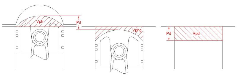
The technique for measuring Vph is to move the
piston down from TDC by a measured distance (Pd) so that its
uppermost point is at least 2mm (0.080”) below the deck and then
to measure the volume of the space from the top of the piston to
the deck – the gross piston head volume (Vphg). The volume
(Vpd) swept by moving the piston down by the distance Pd can be
calculated and subtracted from Vphg to give the true piston
head volume (Vph).
Notes:
The value of Vph will be negative for domed piston.
Pd is also referred to as “piston depression”
Vpd is also referred to as “depression volume”
The method of measuring Vphg and the combustion chamber volume (Vcc) is to fill the space with a measured amount of liquid for which you will need:
Liquid of low surface tension and viscosity. Isopropyl alcohol with some colouring agent added is recommended but other liquids such as Methylated spirits
(in the UK) are probably OK.
Some grease which isn’t readily soluble in the liquid,
A liquid dispensing device (preferably a burette of at least 50cc capacity) capable of resolving to at least 0.25ml.
A Holy Plate - piece of 1/8” clear acrylic (e.g. Plexiglass or Perspex) about 150mm (6in) square with a small hole in the middle through which the liquid can be
dispensed.
To measure the combustion chamber volume (Vcc), install the spark plug and valves. If there’s any chance of leakage past the valve seats then give them a light coating of grease first, Place the cylinder head so that its face is uppermost and level. Apply a light coat of grease around the edge of the combustion chamber and press the Holy Plate firmly down so that the grease around the chamber seals evenly with it. Fill the chamber through the hole in the plate ensuring that there are no trapped air bubbles. Make a note of the exact number of cubic centimetres of liquid drained from the burette in doing so.
To measure the gross piston head volume (Vphg) firstly apply a small amount of grease around the top edge of the piston so that liquid can’t seep past the rings. Move the piston down from TDC by a measured amount (Pd) as described above. Apply grease around the edge of the cylinder bore and measure the volume using the Holy Plate and burette as for measuring the combustion chamber volume.
You should now have measurements for Example
Bore of the cylinder (B). 82 mm
Stroke of the engine (S).
80 mm
Compressed gasket thickness (Gt). 1.7 mm
Bore of the gasket (Gb). 82.5 mm
Volume of the combustion chamber in the cylinder head (Vcc). 39 ml
Gross piston head volume (Vphg) 65.7 ml
Piston depression (Pd) 12.7 mm
Calculations
Calculation of compression ratio is done in 8 stages which, although not complicated, is tedious and prone to human error when using a calculator. A computer programme, CR-CALC.EXE which you can download from this site, performs all the required calculations. Details follow in the Appendix.
If you are intending to use CR-CALC then you can skip the boring arithmetic.
The volume of a cylinder is
πD2H
/4 where:
π
= 3.142
D is the diameter (or bore)
H is the height
If the bore and height are measured in millimetres and the volume is to be in millilitres (cc are the same) then volume = D x D x H x 0.0007854 but if they are measured in inches then volume = D x D x H x 16.387 ml.
In the formulae tabulated below, F is 16.387 if measurements are in inches or 0.0007854 if measurements are in millimetres.
|
Item |
Symbol |
Formula |
Formula applied to example |
Result |
|
Depression volume |
Vdp |
B x B x Pd x F |
82 x 82 x 12.7 x 0.0007854 |
67.070 |
|
Nett piston head vol. |
Vph |
Vphg – Vdp |
65.7 - 67.070 |
-1.369 |
|
Gasket volume |
Vg |
Gb x Gb x Gt x F |
82.5 x 82.5 x 1.7 x 0.0007854 |
9.087 |
|
TDC volume |
Vtdc |
Vcc + Vg + Vph |
39 + 9.087 + (-1.369) |
46.718 |
|
Swept volume |
Vsw |
B x B x S x F |
82 x 82 x 80 x 0.0007854 |
422.482 |
|
BDC volume |
Vbdc |
Vtdc + Vsw |
46.718 + 422.482 |
469.200 |
|
Compression ratio |
CR |
Vbdc / Vtdc |
469.200 / 46.718 |
10.043 |
Using a calculator, work out the result for each line in the table making a careful note of the result as you will need it in the next, or another line later on. For example you need the result for Vdp before you can calculate Vph.
Although you only need the CR to one decimal place it is better to work to at least three places during the intermediate stages.
Appendix –
CR-CALC.EXE (Click to run or save)
CRC-CALC is a small (about 18K) utility to calculate the compression ratio of an IC engine.
Although it is a DOS programme it should run happily under most versions of Windows.
It can be installed in any directory of the user’s computer and run from Start/Run or by creating a shortcut to it. When run from Start/Run it will run in full DOS screen mode. If run from a shortcut, it will run in a window if the shortcut Properties/Screen item is set to Window instead of Full Screen.
The user can set any of the measured engine parameters in alternate units. Linear dimensions can be input in mm or inches and volumes can be input in ml or cubic inches.
For each parameter there are two side-by-side boxes, one for the first unit, e.g. mm and the other for the second, e.g. inches. When a parameter value is edited, the corresponding value in the alternative units box is automatically adjusted. e.g. if you change the cylinder bore from 82 to 100 mm then the inches value is changed from 3.228 to 3.937” automatically.
The calculated compression ratio is automatically updated as soon as a parameter is changed. It enables you to easily see the effect on compression ratio of making any change of dimension.
On exiting CR-CALC the current parameters are saved in a small binary file (CR-CALC.CFG) in the same directory† as CR-CALC.EXE provided that you quit by striking the ESCape key.
It is not saved if you are running in a
window and exit by clicking on the X at the top
right of the window. You can also exit without
saving the current data by using Ctl-End.
†
WARNING: If you open (rather than save) CR-CALC in your browser then, any created CR-CALC.CFG file, may appear on your desktop but can be safely deleted.
CR-CALC does not make any use of the dreaded registry so it can be completely removed just by deleting it and any CR-CALC.CFG file.
Altering your compression ratio
Apart from changing pistons you can adjust your compression ratio by changing the thickness of your head gasket, skimming the top of the block or skimming the cylinder head or a combination of those. All of those, with the exception of increasing the gasket thickness, can only increase the compression ratio. CR-CALC enables you to see what you can alter to achieve a new CR but, obviously, does not take account of effects such as the valves clashing with the piston.
Firstly calculate your current CR, so you should have a note of (1) combustion chamber volume, (2) compressed gasket thickness and (3) piston depression.
Now you can change one or more of those values in CR-CALC until you get the desired CR and note the new values of 1, 2 & 3. The new gasket thickness is self evident. So is the new combustion chamber volume but it doesn’t tell you how much to shave off the head to get the required volume because the combustion chamber is probably an irregular shape – you’ll have to fathom that out for yourself or re-measure the combustion chamber volume after each pass on the machine
that is skimming the head
The difference between the original and new
values for piston depression is the amount you
need to skim from the top of the block.